


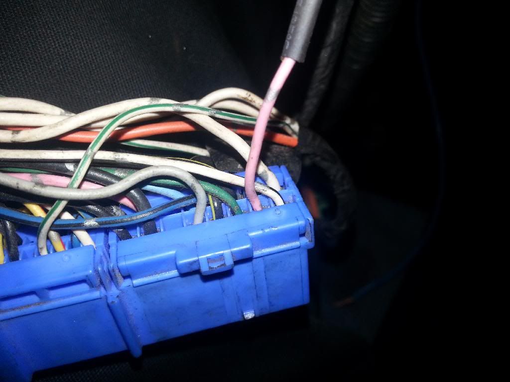
we cut the wire for pin 102 an soldered our own on just incase theres something funky in the harness somewhere..
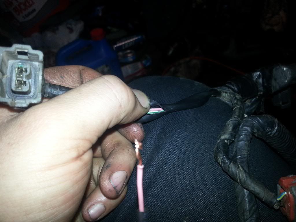
this is the plug that wire used to goto, its no longer going to be used so we zip tied it up
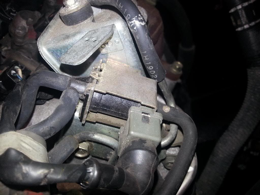
an heres what it connected to on the intake manifold, its just above the throttle body by the egr crap kinda..
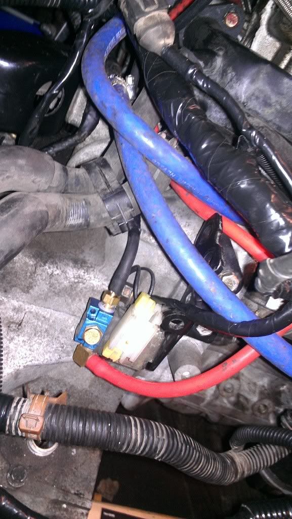
customized a stock solenoid bracket for the mac valve and made a plug for it
we followed the directions from the nismotronic help thing an it works perfectly!
Heres the directions from the help section
EXTERNAL GATE SETUP
Port 1 - Boost source from the intake manifold OR turbo is T’d into the BOTTOM port of the WG
Port 2 - Connect Directly to the TOP port of the WG
Port 3 - OPEN FILTER

Internal WG Setup
Port 1 - OPEN FILTER
Port 2 - Boost Source from intake manifold or turbo
Port 3 - Directly to Internal WG nipple

Boost Solenoid Wiring
Wiring the boost solenoid is very straightforward. There are two wires coming from the solenoid; 1 goes to a switched 12v power source, and the other goes to a PWM output from the ECU (which varies depending on which ECU you are using).
If you are using an SR20DE, KA24DE or RWD SR20DET ECU; then connect the PWM output wire to the stock AIV output on pin 102.
If you are using a FWD SR20DET ECU (GTiR); then connect the PWM output wire to the stock WG solenoid output on pin 111.

big thanks to @JKTUNING and @OnTheChip for making this all possible for us!
this is the plug that wire used to goto, its no longer going to be used so we zip tied it up
an heres what it connected to on the intake manifold, its just above the throttle body by the egr crap kinda..
customized a stock solenoid bracket for the mac valve and made a plug for it
we followed the directions from the nismotronic help thing an it works perfectly!
Heres the directions from the help section
EXTERNAL GATE SETUP
Port 1 - Boost source from the intake manifold OR turbo is T’d into the BOTTOM port of the WG
Port 2 - Connect Directly to the TOP port of the WG
Port 3 - OPEN FILTER
Internal WG Setup
Port 1 - OPEN FILTER
Port 2 - Boost Source from intake manifold or turbo
Port 3 - Directly to Internal WG nipple
Boost Solenoid Wiring
Wiring the boost solenoid is very straightforward. There are two wires coming from the solenoid; 1 goes to a switched 12v power source, and the other goes to a PWM output from the ECU (which varies depending on which ECU you are using).
If you are using an SR20DE, KA24DE or RWD SR20DET ECU; then connect the PWM output wire to the stock AIV output on pin 102.
If you are using a FWD SR20DET ECU (GTiR); then connect the PWM output wire to the stock WG solenoid output on pin 111.
big thanks to @JKTUNING and @OnTheChip for making this all possible for us!
Last edited by JKTUNING
on 2014-08-12
at 23-17-39.


