Okay. KITS FOR SALE.
A kit will include:
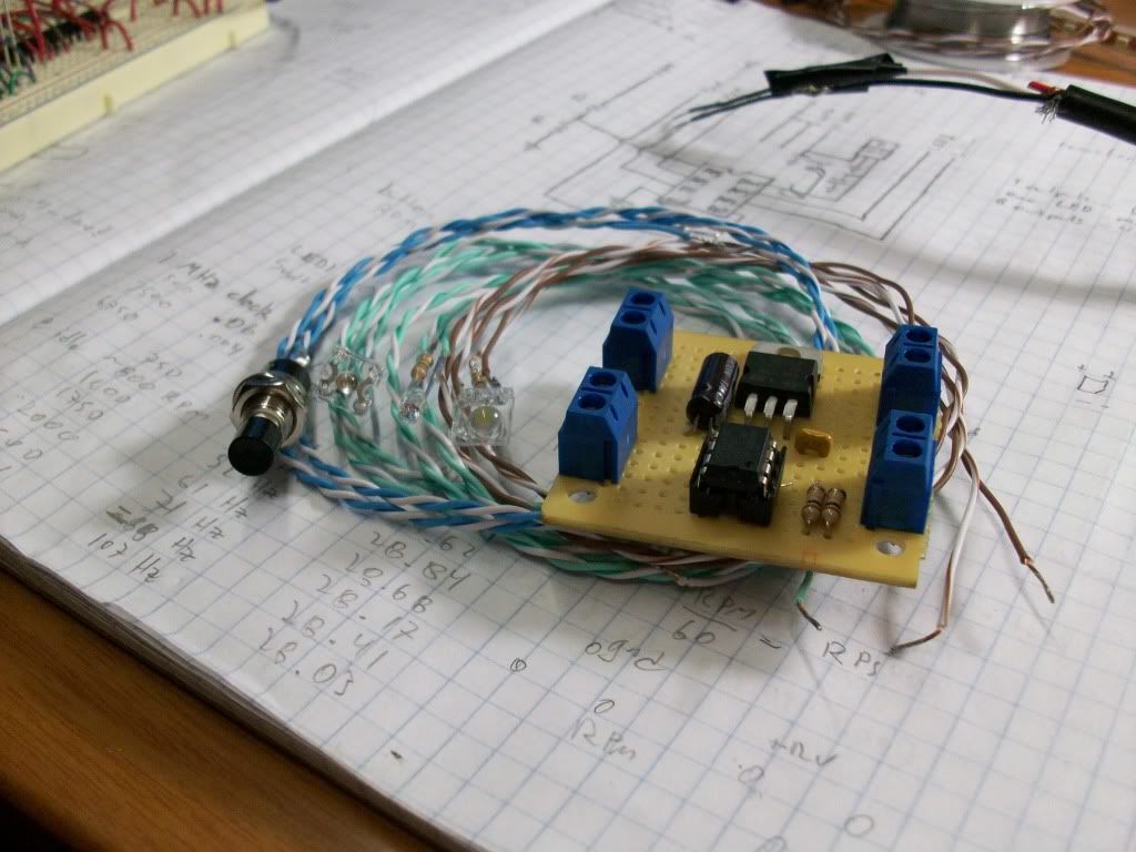
The board.
Three LEDs, style as specified by you.
A push button.
The LEDs will have resistors and two-foot leads pre-soldered, as will the pushbutton. You will have to provide power leads and a wire to a fuel injector wire. If you want to install the tachometer needle LED, some soldering is required.
I have three types of LEDs. Bright green or white, both a larger square LED. Not as bright red, good for tachometer needle, in classic LED shape. Both green and white LEDs are about the same brightness.
Each board can drive three LEDs. I can set up each LED output as you want it. (Switchable and either strobing or constant on when threshold is reached)
I don't have a lot of kits, and I probably wont make more, so here's how it'll work: PM me what you want. Tell me:
What you want each of the three LED outputs to do when the shift point is reached.
What color and style LEDs you want. (From what I have available)
What you want the default shift value to be.
If you want the tach needle LED.
If I can do what you'd like, I'll give you my paypal address, and you can send me $45 and your shipping address. I'll make the kit, test it, make you a video of the kit, and if you're happy with what you see, I'll ship it off to you. If you're not happy, you can have your money back. If you get the kit and it doesn't work as well as it should, you can have your money back. If you get the kit and decide you don't want it... you can't have your money back.

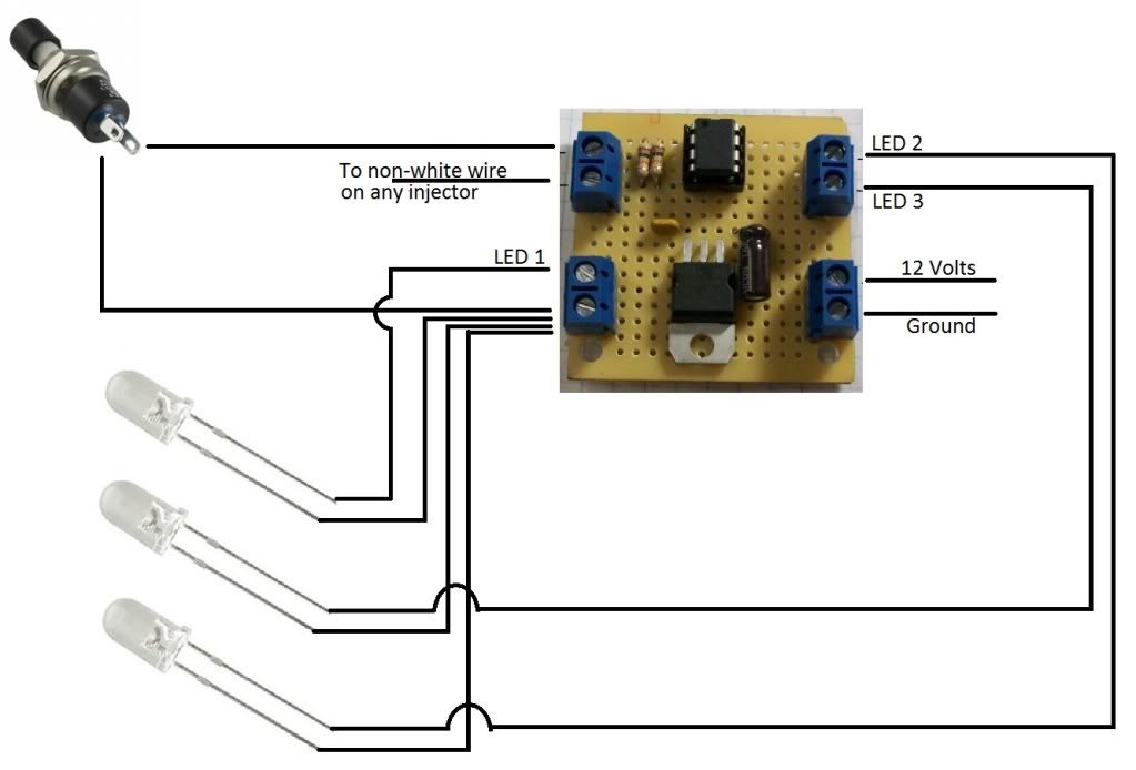
If this install schematic leaves you with any questions, feel free to ask them. If anyone is interested in the tach needle LED I'll put up some photo install instructions for them (though that install is at your own risk!)
The striped wire (+, LED anode) from each LED goes to the lower left connector on the board.
Kit contents:
White vs Green LED:
[youtube]p0gXWDD0u4I[/youtube]
Red vs Green LED:
[youtube]8p18sLAon2Y[/youtube]
Ask questions!


 Be the first to like this post.


