Welcome to the SR20 Community Forum - The Dash.
Register
SR20 forum logo

Thread: 2023 VE build.

+ Reply To Thread
Posts: 1-10 of 153
2009-12-24 09:56:47
#1
2023 VE build.
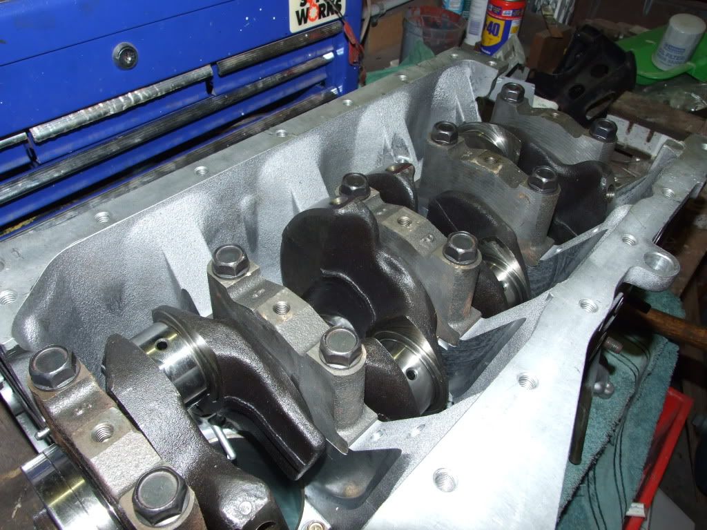
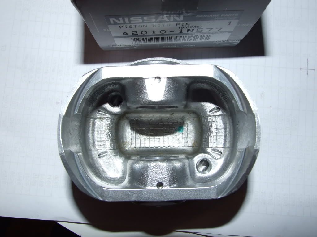
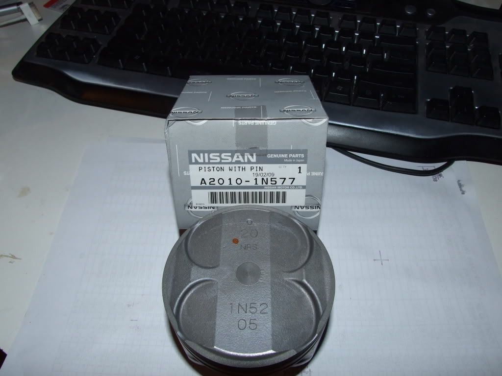
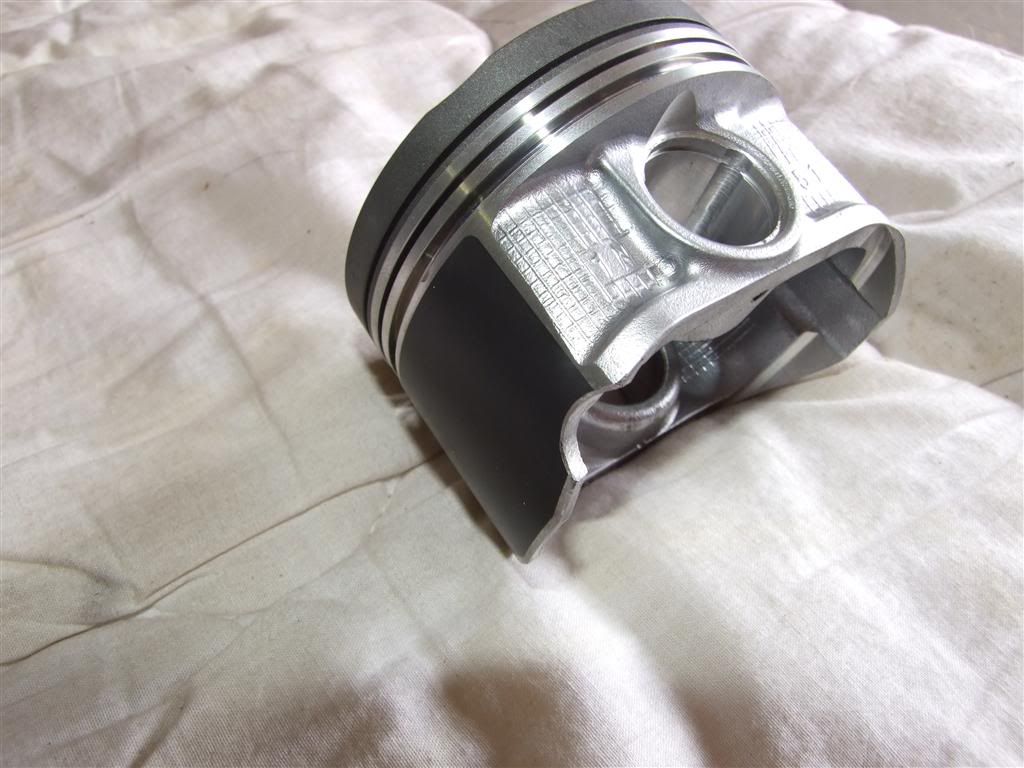
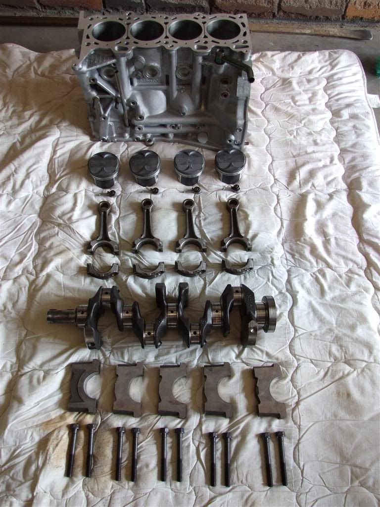
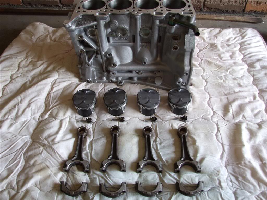
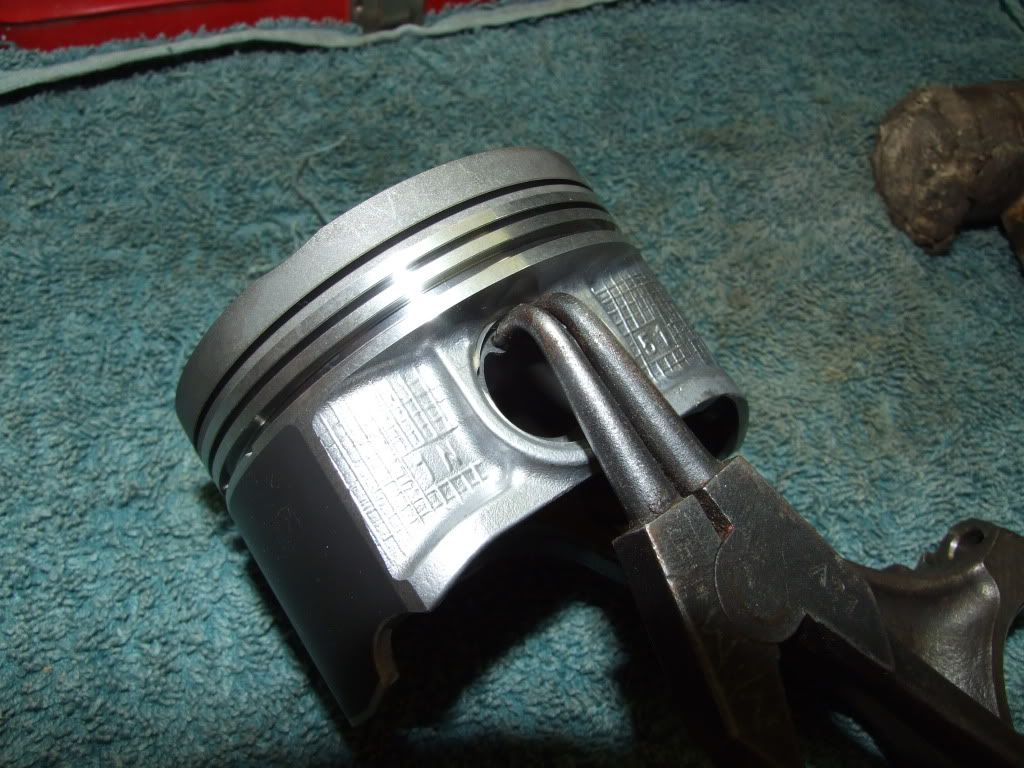
Heres my VE build. 2023cc as per title.


Will be doing a fair few custom mods onto it.

Willupdate with pics and details as i go.


--------------------------------------------------------------------------

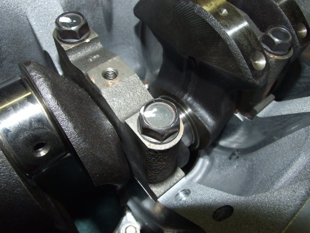
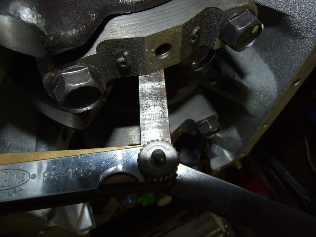
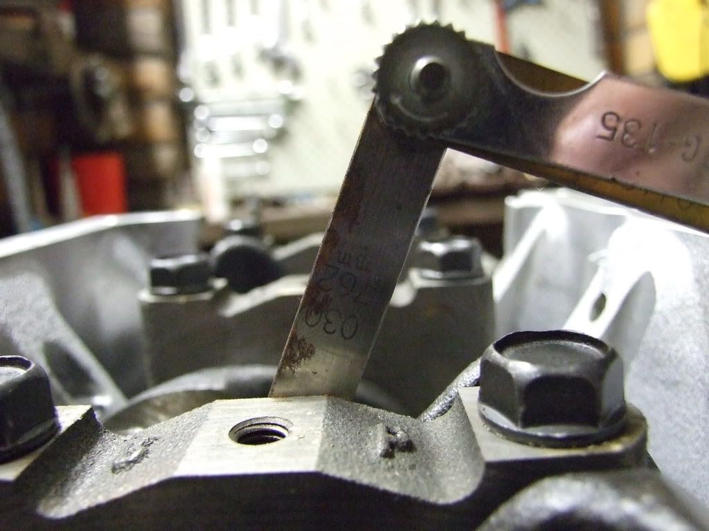
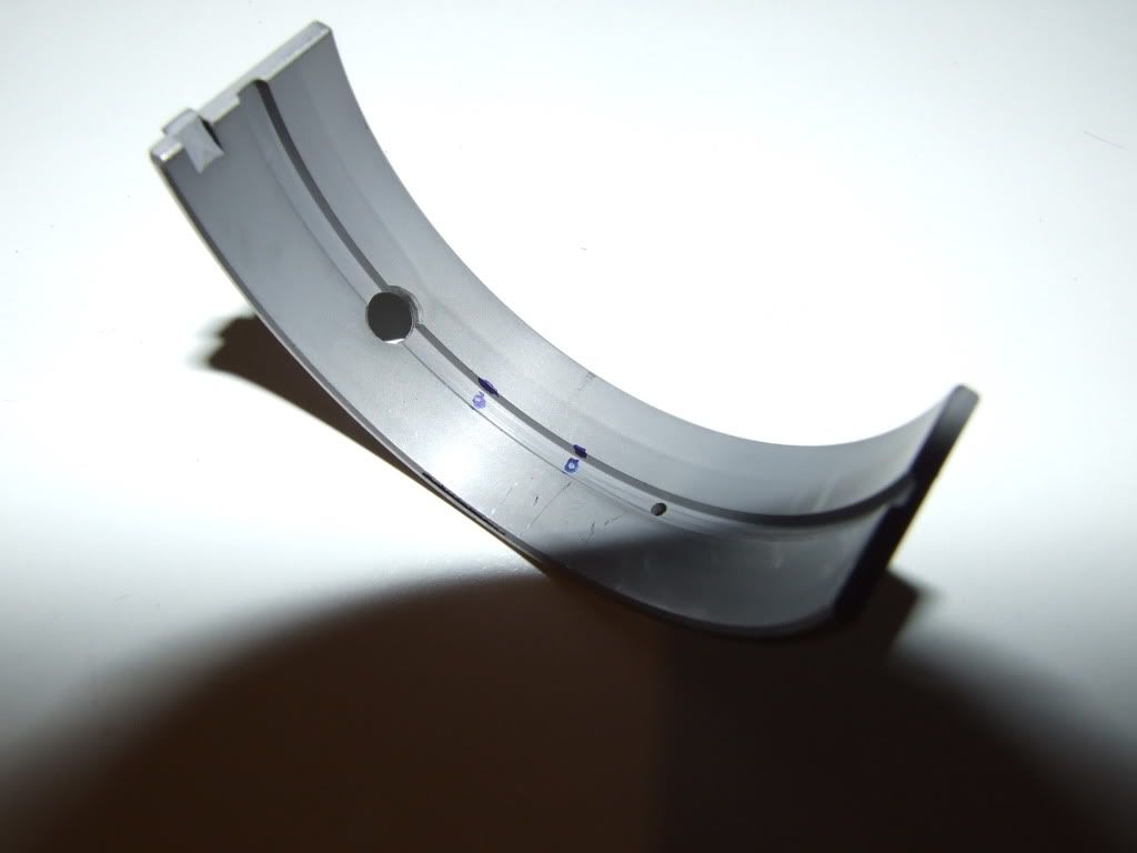
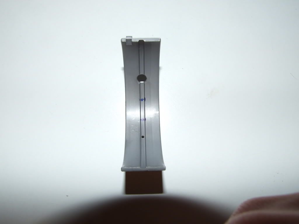
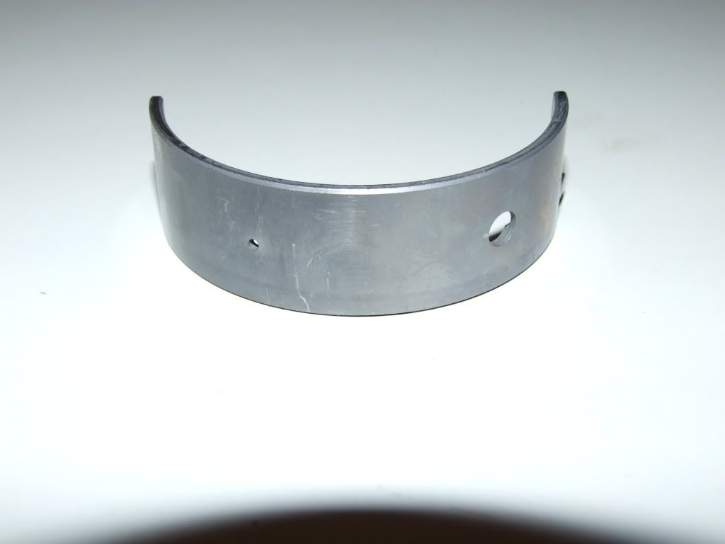
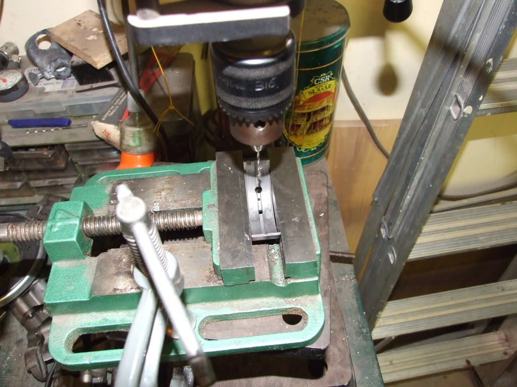
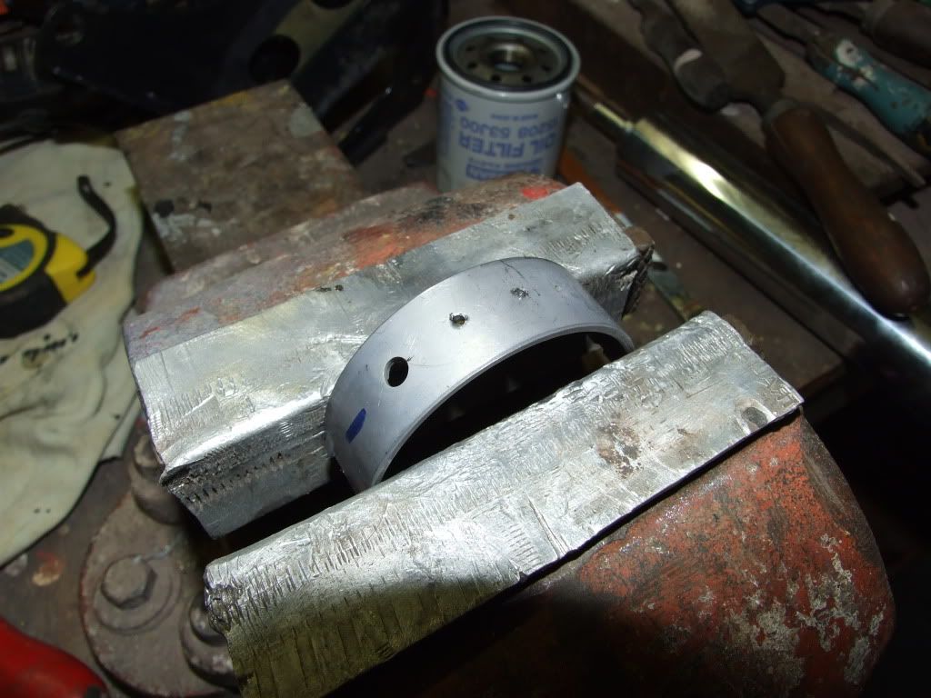
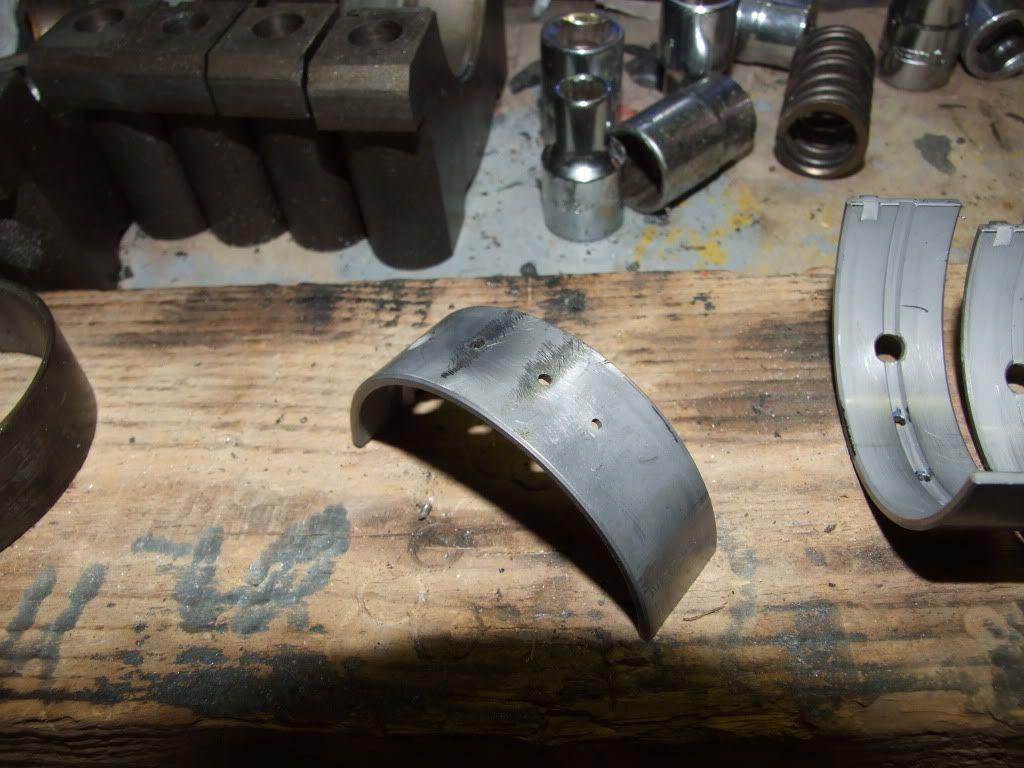
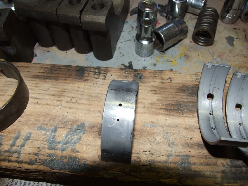
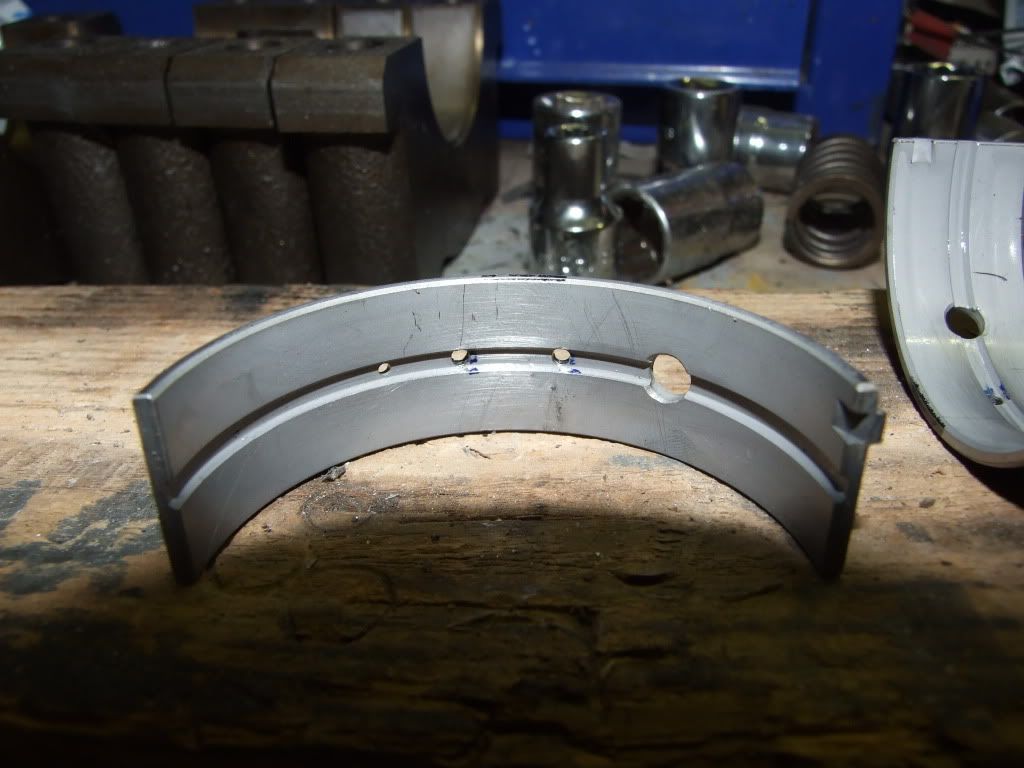
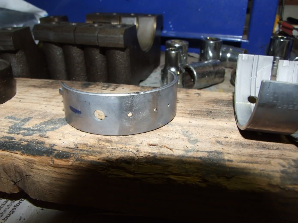
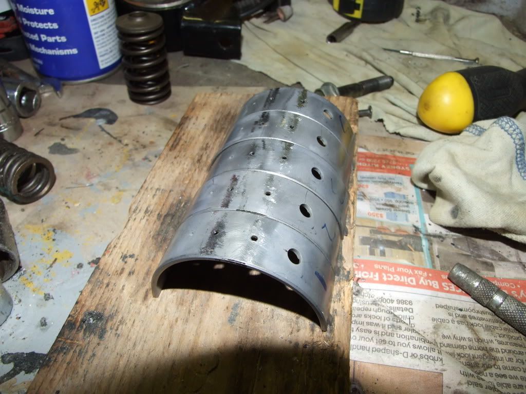
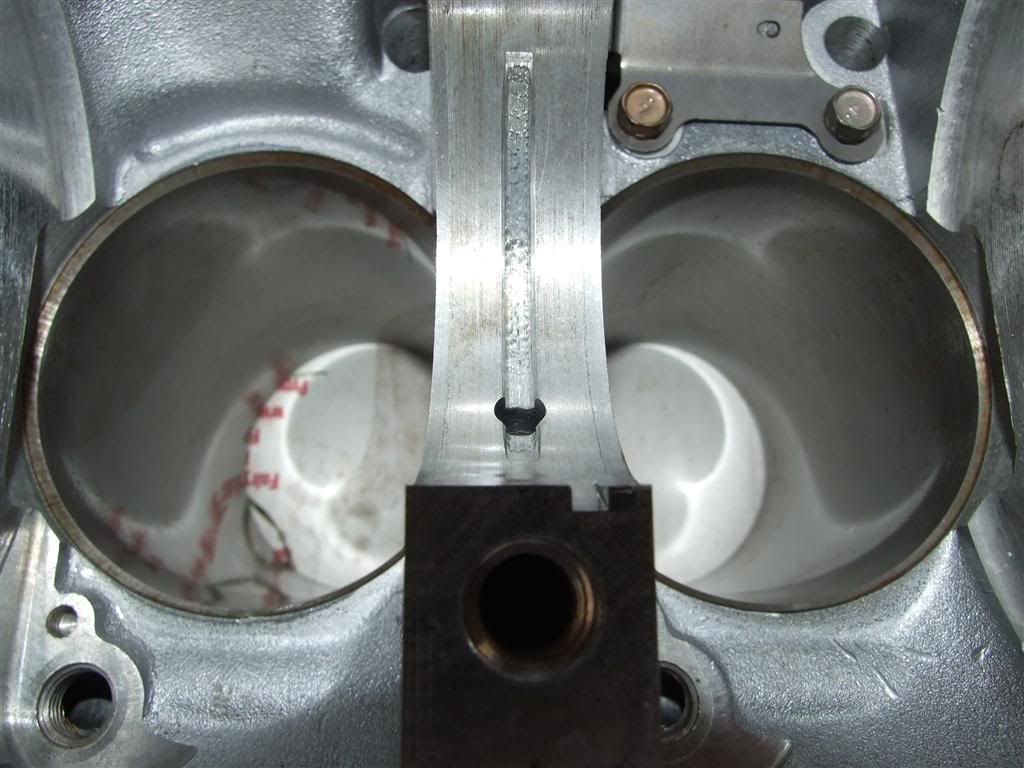
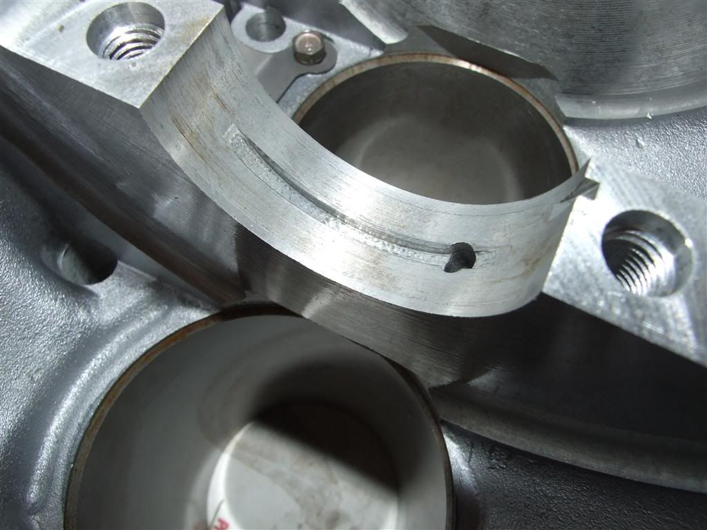
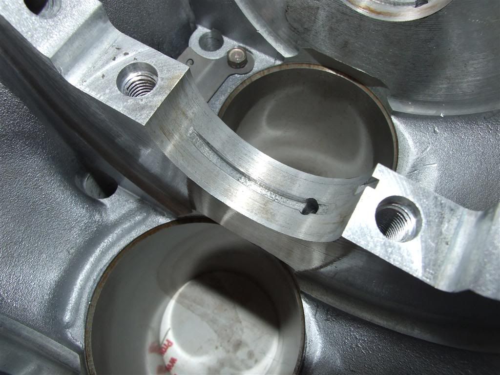
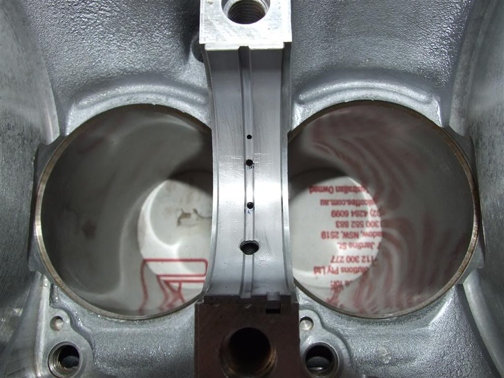
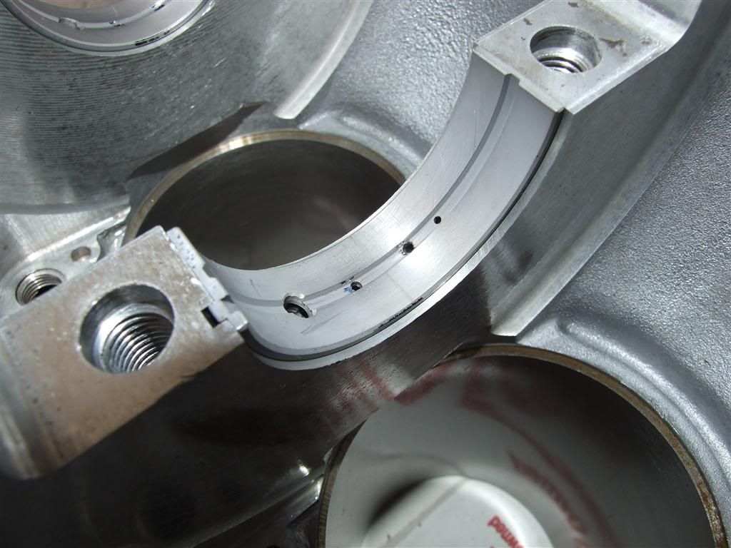
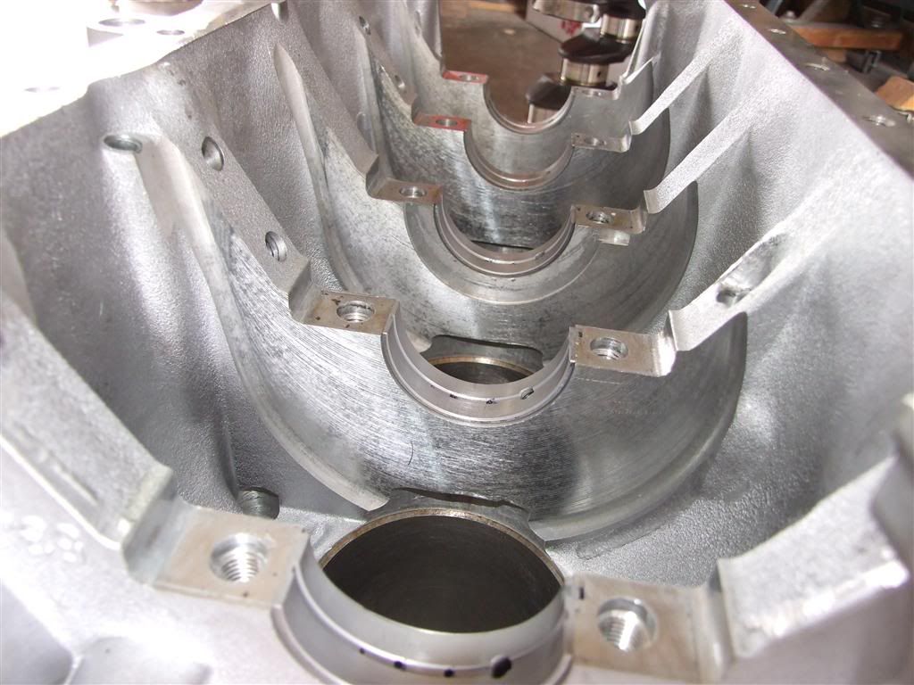
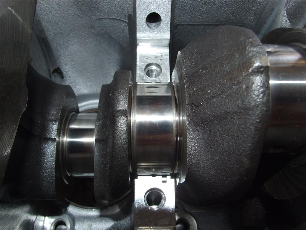
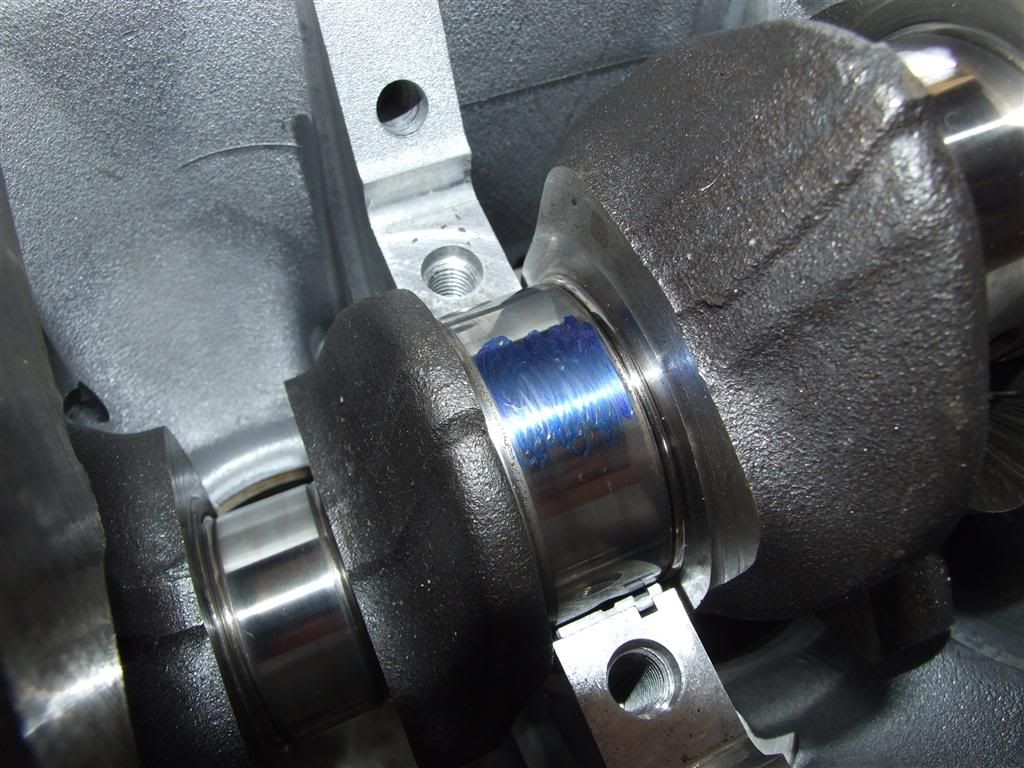
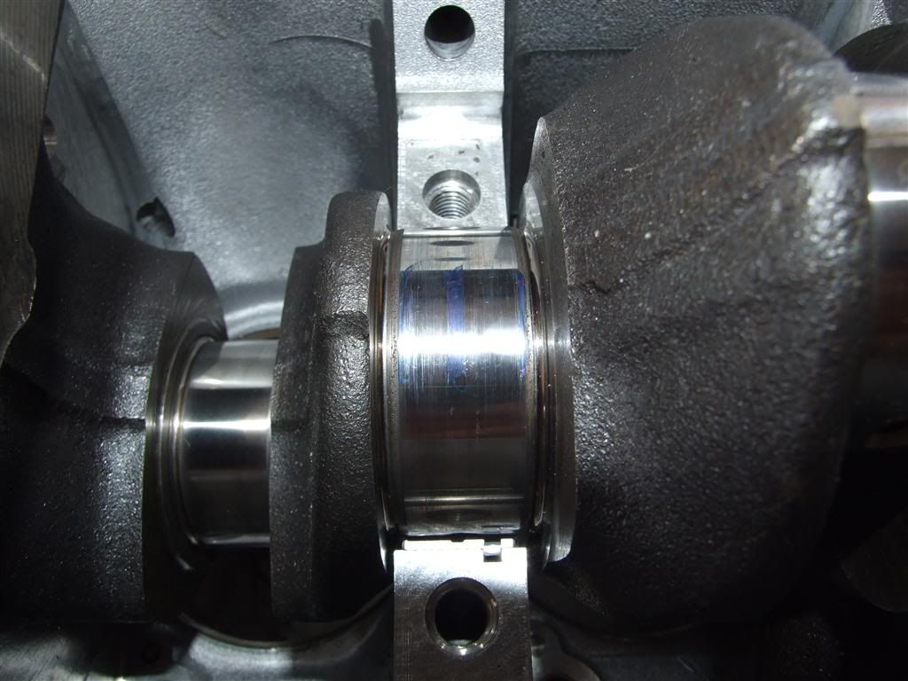
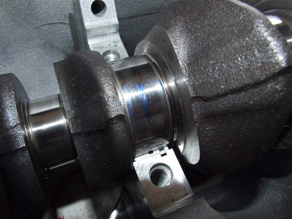
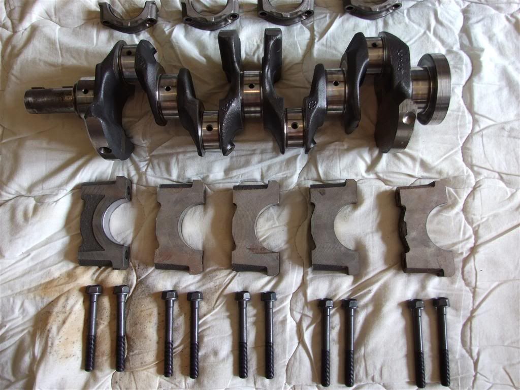
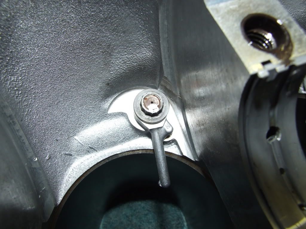
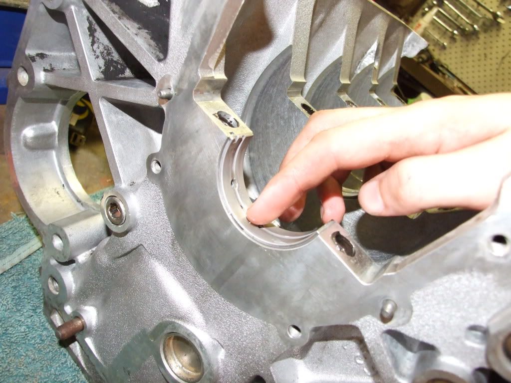
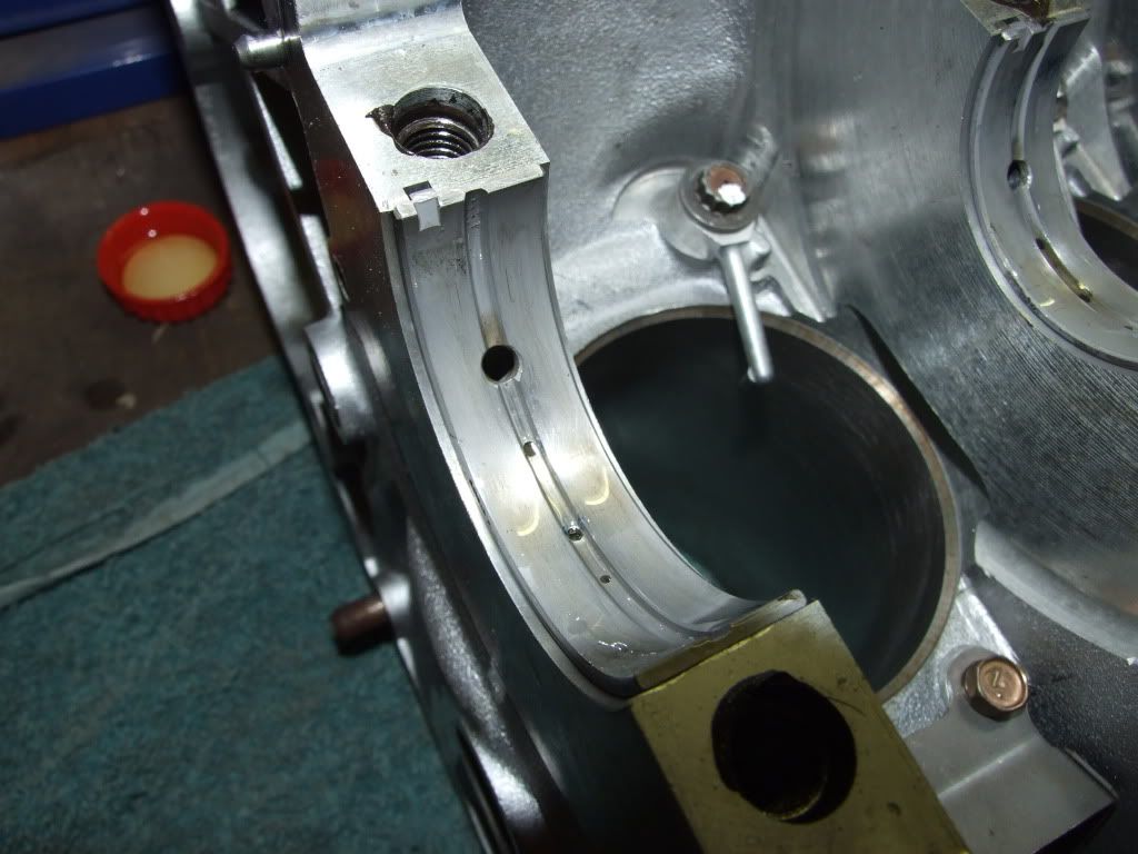
Here are picsutres of my modified main bearings.

I ordered original N1 bearings, however the part number has been discontinued by nissan and replaced by a generic part number for all SR's. In the hope that nissan upgraded all the bearings to have multiple oil feed holes i went ahead and ordered them.

What i got was stock, regular single large feed, with second pin hole bearing shells. Not to happy to say the least. me being a tight arse, and not wanting to waste money - i modified them a little. Pics below. Extra oil feed holes will help with oil flow and journal temp, not that its 100% needed, but all the little extra things will add up. I dont want to risk it runing a main dry, especially on the track or through a tough run, because i couldnt put 45mins of my time away to improve them.

Pic warning ahead.


2009-12-24 09:57:13
#2
N1 oversized pistons - 20thou.

Low friction Skirt coating, top coating which covers to the first compression ring.

These pistons need to be notched on the lower skirt for oil squirter clearance.

Interestingly, they are made by Unisia Jecs - the company that did all the electronics for nissan, and used to run Skyline and Sivlia race teams in Japanese touring cars. Unisia Jecs are now owned by Hitachi.


2009-12-24 09:57:34
#3
Got some more parts today.

Extreme button clutch - sprung centre - 900kg clamp.

Extreme clutches seem to be using LUK gear - this is a LUK pressure plate.

JUN motorsport flywheel (P10 4.1kg version)

I had the pressure plate machined and balanced to match the flywheel so the combination is balanced.


Seing as the flyhwheel is a raw surface, im not sure exactly when its going in. Normally i would spray it with lanolin or WD40 to stop any corrosion. Instead i had to improvise - old school method of rust protection!!!


Add a small bit of engine oil - mix with degreser thoroughly.


Then Brush onto flywheel surface with newspaper or a cloth.


Will be good for months:thumbsup:
2009-12-24 09:58:14
#4
Heres my little bit of sump modding.


The factory sump has an excellent top tray to stop oil splashign around and escaping the lower pan.

I will be addding a steel crank scraper to wipe excess oil off the crank. Kevin Johnson from the US is making one up - hopefully it will arrive by christmas.

Home


I will be cutting the lower buldge out of the pan - this buldge is right next to the oil pickup - not preferable for a tack setup with oil splashing around the pan!


You can see the steel plate that helps stop oil from escaping the lower pan.


Heres the gay bump in the lower pan. This bump is there for acces to the trasnmission on auto FWD SR's. This will be cut out and squared off.


Heres where i am putting my sump baffles.

Im putting the baffles at the front of the lower pan. Under heavy brakes it will help trap oil near where the pickup sits, but on acceleration - any oil that has gotten past it, can flow to the back of the pan - back around to the pickup.

You will notice there is a small lower baffle along the floor on a 45 degree angle from the main baffle - this is to slow oil moving away from the pickup - pushing it upwards towards that centre steel plate shown above that covers the whole of the lower sump.


2009-12-24 09:58:38
#5
Cut out the hump today.


Had to cut out a 1 piece 100mm x 100mm piece of steel. It has to be one piece for extra strength. If i welded dual pieces in an squared them off i would have issues with strngth if anything hit the sump.

After about 30mins of malleting, and needing - it fits great.


Ground the area around the patch for welding. Has to be good wide grounds, i want good penetration through both sheets and through the bottom for dealing and strength.


Jigged up and ready to be tacked.


All lined up - now to start fill welds.


Good penetration to the underside - will finsih the underside welds tomorrow night.


2009-12-24 09:59:19
#6
The stock intake manifold is pretty well designed.

The only flaws are the surface cast and the fact the casting is shifted pretty badly.

Each stage of the manifold is matched. You will notice there is no picture of the opening of the manifold to the head. I have worked in this area, but i wont be showing what ive done here - this is a secret (insert iamhappy46 pic here?)....Providing the motor makes good power - i will post pics - until then its a secret bit of work (avoid embarrassment if it doesnt work:lol


When i say shifted, most of the top half of the ports overlapped the lower intake ports by around 3-5mm. This would seriously kill flow in top end. With a little hand work, you can rework the ports so they match the two halves of the manifold. After giving them a bit of hand work, i went over the intake surface of the ports with a rotarty emery brush. This took out all the burs and gave it a nice even cleanup.

One of the weird things with the 16/20ve manifold is that they are tapered off at the each segment of each section of runner. For example - the top half runner squeezes in tighter right before the join (about 5-7mm in diamter less!!!!) then opens back up again to the last stage of the runner to the head. Having this would be bad for velocity. I stayed away from taking out the inside of the runners, to help balance the flow of the manifold. Too many drops and spike in pressure would be bad for top end. (This is of my beleif anyway).

pics are self explanatory!!


2009-12-24 09:59:57
#7
Got the black back from the Machinist/builder today.

Heres some pics of the factory slotted bottom journals.


Now with my modified bearing shells.


Now to test the shell and make sure they are 100% true, as well as checking the crank journals are 100% true.

Line up the crank:


Mark the crank journal surface with texter.


Rotate the crank - this will wipe off the texter, and give you an indication if the bearing is 100% true to the crank. The only marks i should see is the very outer edge of the crank (bearing shell does not extend this far) and the centre where the oil feed channel is.

Result:


Sufficed to say im quite chuffed:boobies: The crank could not have better a grade to begin with, and the block and bearings are 100% spot on. This means no hand file work for me!


More pics to come of notched pistons and other gear later tonight.
2009-12-24 10:00:30
#8
We had to notch the base skirt of the N1 piston to clear the piston cooling nozzles.

The stock 16ve stroke is 68.7mm. Now that im running 86mm stroke - it was line ball for having to notch them. Here is the result.


Heres an exploded bottom end i prepared earlier!

SR16VE block. Bored 0.25 OS.
Piston Cooling Nozzles.
N1 Oversized .20 Pistons.
S13 DET rods.
4cw 86mm - 2ltr Crank
Cast Iron Factory Main caps.
Nismo N1 Main studs.


2009-12-24 10:00:56
#9
Rods and Piston went together earlier this evening.


Pin all lubed up sliding into action!


Retainer Circlip:


Some new friends to help at high RPM:


Oil squirters installed - torqued and thread locked. Note the white dab of whiteout - this is so i know when it comes time to triple check the engine - these have been torqued.


Pre Oiling the bearing shells before crank install:

Note Castrol GTX used - mineral oils are brilliant for running in. You dont want any modifiers in the oil to help protect or lubricate. The first 500k's is the hardest and most wearing time on the engine. It is literally skimming and grinding itself, so each journal and ring will mate against each other.


\


Crank installed with main caps:


Caps torqued and marked. Ive strecthed and torqued the Nismo studs twice. They are all now marked. I have one finally loosen and retrque before sealing the engine.


Here im checking crankshaft end play - Stock tolerance is up to 0.24. The absolute upper tolerance is 0.30 on a worn journal.

I double checked with a dial gauge as well. Im absolutely cheering about the result.

Check these figures:thumbsup:


2009-12-24 14:28:23
#10
Nice work! I wish I had time to build a motor like that...
+ Reply To Thread
  • [Type to search users.]
  • Quick Reply
    Thread Information
    There are currently ? users browsing this thread. (? members & ? guests)
    StubUserName

    Back to top