Welcome to the SR20 Community Forum - The Dash.
Register
SR20 forum logo

Thread: Turbo setup vaccuum diagram

+ Reply To Thread
Posts: 1-10 of 28
2012-11-21 04:12:10
#1
Turbo setup vaccuum diagram
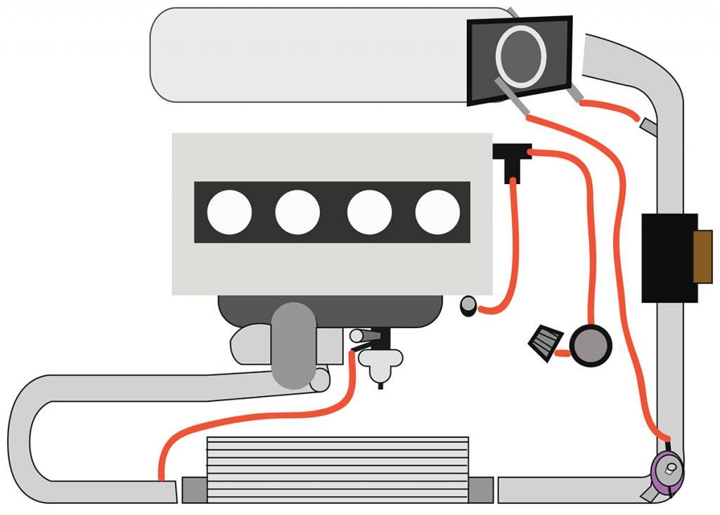
Hey guys im having a hard time getting some vacuum question answers on my turbo setup so i made up a lil diagram. I made the vacuum lines red and want to know if they're connected in the proper/optimal location. If anyone (im lookin at you benfenner, thanks in advance) can help id really appreciate it.

Last edited by blurr.rt.by.you on 2012-11-21 at 04-13-06.
2012-11-21 04:29:55
#2
The bov hose should go after the throttle body on the manifold somewhere, the wastegate hose can go to where the bov's currently hooked up in your picture (if thats the little vac nipple on the throttle body that is) and you can run that oil catch like you have it, or if you went draw through you could take the filter off and hook it to the intake pipe (or not).

I'm not a fan of blow through, had really bad luck with it, but others have had good luck, if I were to try it again I'd have to use one of the billet maf housings.

Oh and I assume the hose after the maf is going to the IACV, if so that's correct.
Last edited by lynchfourtwenty on 2012-11-21 at 04-30-39.
2012-11-21 04:43:28
#3
Originally Posted by lynchfourtwenty
The bov hose should go after the throttle body on the manifold somewhere, the wastegate hose can go to where the bov's currently hooked up in your picture (if thats the little vac nipple on the throttle body that is) and you can run that oil catch like you have it, or if you went draw through you could take the filter off and hook it to the intake pipe (or not).

I'm not a fan of blow through, had really bad luck with it, but others have had good luck, if I were to try it again I'd have to use one of the billet maf housings.

Oh and I assume the hose after the maf is going to the IACV, if so that's correct.


Awesome, thank you very very much.
2012-11-21 05:12:20
#4
no prob, i liked the diagram, made it fairly easy to help you, keep up the good work.
2012-11-21 05:17:54
#5
Originally Posted by lynchfourtwenty
no prob, i liked the diagram, made it fairly easy to help you, keep up the good work.


thanks i wanted to make it as close to how it really looks.
2012-11-21 05:33:02
#6
I agree with lynchfourtwenty about how you should route your hoses.

FYI, @BenFenner is currently on a hiatus of sorts. No one seems to know what happened to him.

-G
Last edited by gomba on 2012-11-21 at 05-38-55.
2012-11-21 15:10:05
#7
Originally Posted by gomba
I agree with lynchfourtwenty about how you should route your hoses.

FYI, @BenFenner is currently on a hiatus of sorts. No one seems to know what happened to him.

-G


Thanks G, hope all is well with Ben. I was actually considering putting the oem catch can back in, not the stock location but using the same lines and ports.
I actually read some of that blow-by gas thread.
2012-11-21 15:25:41
#8
Originally Posted by gomba
I agree with lynchfourtwenty about how you should route your hoses.

FYI, @BenFenner is currently on a hiatus of sorts. No one seems to know what happened to him.

-G


I think he took a permanent hiatus after his mod abilities were stripped.
2012-11-21 16:17:10
#9
He's taking a break from it all. He did mention on how much more free time he has now, forum does eat up a lot of all our days
2012-11-22 17:49:37
#10
Make sure on external wastegates to used the bottom nipple. The top one is meant for electronic boost controllers
+ Reply To Thread
  • [Type to search users.]
  • Quick Reply
    Thread Information
    There are currently ? users browsing this thread. (? members & ? guests)
    StubUserName

    Back to top